
Serial to Ethernet Converter for PLC and SCADA: What Compatibility Should You Check?
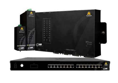
Serial to Ethernet Converter: PLC/SCADA Checklist
Connecting a serial to Ethernet converter between a legacy PLC and a modern SCADA system looks straightforward on paper – plug in the serial side, connect the Ethernet side, and data should flow. In practice, compatibility issues between the PLC’s communication settings, the converter’s configuration, and the SCADA system’s expectations are one of the most common causes of failed or unreliable integrations, often discovered only after installation when data doesn’t appear correctly (or at all) on the SCADA dashboard.
For facilities specifically working with Modbus-based equipment, a Modbus serial to Ethernet converter adds another layer of compatibility considerations – register mapping, function code support, and addressing conventions that need to align between the PLC and the SCADA system for data to translate correctly.
This guide walks through exactly what compatibility factors to check before connecting a serial to Ethernet converter between a PLC and SCADA system, so the integration works correctly the first time.
Why Compatibility Checks Matter More Than the Converter Itself
It’s tempting to treat a serial to Ethernet converter as simple, interchangeable hardware – plug in any unit and it should work. In reality, the converter is only one piece of a three-part compatibility chain: the PLC’s serial communication settings, the converter’s configuration, and the SCADA system’s expected data format all need to align. A mismatch at any point in this chain results in no data, garbled data, or data that appears but doesn’t mean what the SCADA system assumes it means.
Key Compatibility Factors to Check Before Connecting
1. Serial Protocol Match
Confirm the PLC’s native serial protocol – most commonly Modbus RTU, but potentially a proprietary protocol depending on the manufacturer and age of the equipment – matches what the serial to Ethernet converter supports. A converter built for Modbus RTU-to-TCP conversion won’t work correctly with a PLC using a different, unsupported serial protocol.
2. Baud Rate and Serial Communication Settings
Verify the PLC’s baud rate, parity, data bits, and stop bits settings match exactly what’s configured on the converter. Even a protocol match won’t produce usable data if these underlying serial communication parameters don’t align – this is one of the most common, and most overlooked, sources of connection failures.
3. Modbus Function Code Support
For Modbus-based integrations specifically, confirm the Modbus serial to Ethernet converter supports the specific Modbus function codes your PLC uses (such as Read Holding Registers, Write Single Coil, or Read Input Status). Some lower-cost converters support only a limited subset of function codes, which can cause specific data points to fail to transfer even when the basic connection otherwise works.
4. Register and Address Mapping
Verify how Modbus register addresses on the PLC side correspond to the addresses the SCADA system expects to read from. Address offset conventions can differ between manufacturers (some start register numbering at 0, others at 1, for example), and a mismatch here is a common cause of SCADA systems displaying incorrect or garbled values even when the physical connection is working correctly.
5. Ethernet Network Configuration
Confirm the serial to Ethernet converter’s IP addressing scheme, subnet configuration, and port settings align with your facility’s network architecture and the SCADA system’s expected connection parameters. This includes verifying whether the converter operates in TCP server mode, TCP client mode, or UDP mode, depending on how your SCADA system initiates communication.
6. SCADA System’s Supported Communication Modes
Check whether your SCADA system expects to communicate via Modbus TCP directly, or whether it requires the data to appear through a virtual COM port (with the converter handling the network transport transparently). This determines whether you need a converter supporting virtual COM port redirection software, or one that provides straightforward Modbus TCP output the SCADA system can read natively.
7. Polling Rate and Timing Compatibility
Confirm the converter can handle the polling frequency your SCADA system uses to request data, particularly for applications requiring near-real-time updates. Some converters introduce latency when bridging serial-to-Ethernet communication, which can become problematic if the SCADA system’s polling rate exceeds what the converter and the underlying serial connection can reliably support.
8. Multiple Device Support (If Applicable)
If the converter needs to bridge communication for multiple serial devices on the same Modbus RTU network (a multi-drop configuration), confirm it correctly handles addressing for each individual device and doesn’t introduce conflicts when the SCADA system polls multiple devices through the same gateway.
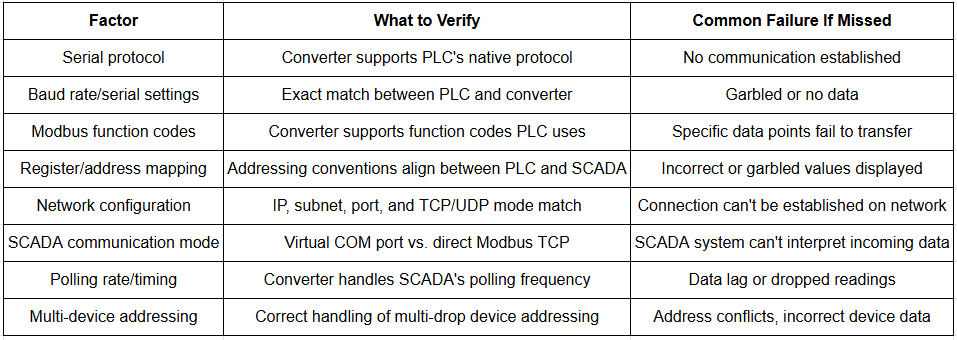
PLC-to-SCADA Compatibility Checklist for Serial to Ethernet Converters
Troubleshooting Common Compatibility Issues
If a serial to Ethernet converter is installed but data isn’t appearing correctly in your SCADA system, work through these common culprits in order:
- Verify physical connections – confirm serial wiring (TX/RX/GND) is correctly connected and Ethernet cabling is properly seated
- Confirm serial settings match exactly – baud rate, parity, data bits, and stop bits must be identical on both the PLC and converter
- Check network connectivity – ping the converter’s IP address to confirm basic network reachability before troubleshooting protocol-level issues
- Review register mapping documentation – compare the PLC manufacturer’s register map against what the SCADA system is configured to read
- Test with diagnostic software – many converter manufacturers provide configuration utilities that can confirm whether the converter itself is receiving and translating data correctly, isolating whether the issue is upstream (PLC) or downstream (SCADA) of the converter
Why a Dedicated Modbus Serial to Ethernet Converter Simplifies Compatibility
For facilities working primarily with Modbus-based PLCs and instrumentation, a Modbus serial to Ethernet converter purpose-built for this specific protocol often simplifies the compatibility checking process considerably. These converters typically include built-in register mapping tools, pre-configured function code support for common Modbus operations, and diagnostic utilities specifically designed around Modbus troubleshooting – reducing the general protocol-matching complexity down to a more focused, well-documented configuration process.
Frequently Asked Questions
What should I check before connecting a serial to Ethernet converter to a PLC?
Check that the converter supports the PLC’s native serial protocol, that baud rate and serial communication settings match exactly, that Modbus function codes (if applicable) are supported, that register addressing aligns with what the SCADA system expects, and that network configuration settings match your facility’s infrastructure.
Why isn’t my SCADA system receiving data through a serial to Ethernet converter?
Common causes include mismatched serial communication settings (baud rate, parity) between the PLC and converter, incorrect register or address mapping between the PLC and SCADA system, network configuration mismatches, or the converter not supporting the specific Modbus function codes the PLC uses.
What is a Modbus serial to Ethernet converter used for?
A Modbus serial to Ethernet converter is specifically designed to convert Modbus RTU serial communication (commonly used by PLCs and instrumentation) into Modbus TCP Ethernet format, allowing Modbus-based legacy equipment to integrate with modern Ethernet-based SCADA and MES systems.
Does register mapping matter when connecting a PLC through a serial to Ethernet converter?
Yes, significantly. Even with a correctly functioning physical and protocol connection, mismatched register addressing between the PLC and the SCADA system commonly results in incorrect or garbled data values, since different manufacturers sometimes use different addressing offset conventions.
How do I troubleshoot a serial to Ethernet converter that isn’t working with my SCADA system?
Start by verifying physical wiring connections, then confirm serial communication settings match exactly between the PLC and converter, check basic network connectivity to the converter’s IP address, review register mapping documentation against the SCADA configuration, and use the converter manufacturer’s diagnostic software to isolate whether the issue is upstream or downstream of the converter.
Check Compatibility Before You Connect
Successfully integrating a serial to Ethernet converter between a PLC and SCADA system depends on verifying compatibility across protocol support, serial communication settings, register mapping, and network configuration – not simply connecting the hardware and assuming it will work. For Modbus-based integrations specifically, a dedicated Modbus serial to Ethernet converter with built-in mapping and diagnostic tools significantly simplifies this process.
At Avyanna Tech, we help engineers verify PLC-to-SCADA compatibility and select the right serial to Ethernet converter for their specific protocol and integration requirements. Contact us to explore our full range of converter and gateway solutions and get your PLC and SCADA systems communicating correctly from the first connection.



[email protected]